SMS

Utilizing SMS's Gravity Waves Tools

Are you working with a coastal model in the Surface-water Modeling System (SMS) that includes a representation of how particles move through a mesh or grid? Did you know that the toolbox has Gravity Waves tools, which can help you visualize and find data about those particles more easily? This blog post will give you an overview of both the Gravity Waves Courant Number tool and the Gravity Waves Time Step tool and how they can help you with your ocean models such as ADCIRC.
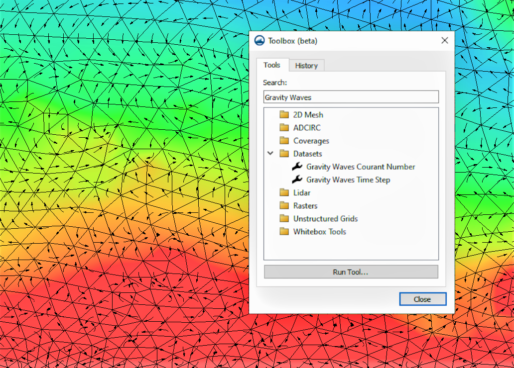
Gravity Waves tools in the SMS Toolbox

The Courant number is a value that represents the amount of time a particle stays in the cell of a mesh or grid. The purpose of the Gravity Wave Courant Number tool is to help maintain the stability of a numerical engine and, potentially, to help choose the most suitable time step measurement. If the methods used to solve numerical problems are restricted by the Courant condition, things can become unstable if the Courant number goes beyond the allowed limit. By looking at the highest Courant number in the dataset, you can get an idea of how stable the mesh is with respect to the chosen time step.

There are three necessary input parameters for the Gravity Waves Courant Number tool, the first being a dataset. This tool requires a dataset that represents the particle’s velocity magnitude. Second, you need to enter a gravity value. Lastly, you’ll enter a computational time step value. For the output parameters, you’ll choose a name for the new dataset. It should be something short and easily recognizable, possibly referencing the input dataset.

The Gravity Waves Time Step tool functions as somewhat the opposite of the Gravity Waves Courant Number tool. The purpose of the Gravity Waves Time Step tool is to calculate the time step needed to achieve the desired Courant number, based on the provided mesh and velocity field. You can then choose a time step for analysis that is equal to or greater than the highest value in the resulting dataset of time steps.

The required input parameters for the Gravity Waves Time Step tool are first, an input dataset, which should be set for depth. Note that it is important that the dataset is specifically for depth, not elevation. Second, enter a gravity value. Lastly, enter the Courant number you’re searching for. Choosing a value for the Courant number under the maximum threshold may increase the stability of the computation because the resulting computation is approximate. The output parameters are where you’ll specify a name for the new dataset. As with the Gravity Waves Courant Number tool, the name should be something short and descriptive.

Try out the Gravity Waves tools for yourself, and see what they can do for your SMS project today!
Blog tags: 

Converting an Unprojected Raster to Vector Maps in SMS

In the field of hydraulic engineering, understanding flow dynamics in channels is crucial for effective design and analysis. Converting unprojected rasters with u and v components from a Large Eddy Simulation(LES) model to a vector map in the channel can provide valuable insights. However, this process can be challenging without the right workflow. In this post, we will explore one approach to achieve this in SMS.

  1. Preparing the Data
    To begin, project component rasters to the correct coordinate system. This ensures that the data is in the correct coordinate system for further processing. This can be done in SMS by importing the raster data in the GIS module. Then use the projection command
  2. Importing and Triangulating the Ugrid
    Next, drag the projected rasters in and convert the u component raster to a Ugrid format using the Raster to Grid tool in the toolbox for SMS 13.2. However, since the resulting Ugrid is created from a raster, the data points are not triangulated for proper interpolation. To address this, select the Ugrid in the project explorer and choose Cells | Triangulate. This allows the data to be interpolated across the surface accurately.
    Alternatively, you can create your own UGrid that encompasses the raster area. Make certain the UGrid has the correct projection.
  3. Incorporating Bankfull Channel Bathymetry
    To add the bankfull channel bathymetry from a raster, interpolate the bankfull elevation to the UGrid points. Use the Data | Map Elevation command to overwrite the existing Z dataset with values from the bankfull dataset. This step ensures that the bathymetry aligns with the UGrid for an accurate representation of the channel.
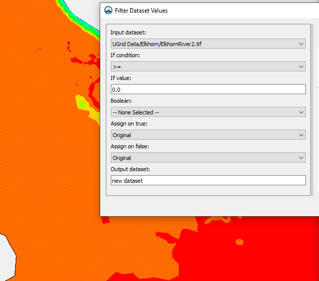
  4. Example of the Filter Dataset Values tool
  5. Displaying Vectors and Refining the Results
    After combining the u and v components, display the resultant vectors. However, it is common to encounter null vectors outside the channel, which may disrupt the visualization. To address this, utilize the filter and map activities in the dataset toolbox. These tools enable you to mask or remove the null vectors, ensuring a clean representation of the flow hydraulics in the channel.

By following this workflow, you can effectively convert unprojected rasters with components from an LES model to a vector map in the channel using SMS. Proper triangulation, incorporation of bathymetry data, and handling null vectors are critical for accurate visualization of flow dynamics. SMS proves to be a valuable tool in streamlining this process, empowering professionals to gain deeper insights into channel hydraulics and make informed decisions for various engineering applications.

Try out working with raster data in SMS today!

Blog tags: 

New Unstructured Grid Generation Tools in SMS 13.3

The Surface-water Modeling System (SMS) allows use of unstructured grid (UGrid) geometries with multiple numeric models. With that, we have been adding functionality to make generating UGrids easier and more convenient. The toolbox in SMS offers many tools to help speed up UGrid creation and simplify the process. SMS 13.3 beta offers the same tools as before, as well as some new ones. As of now there are fifteen tools under the Unstructured Grids folder in the toolbox. The tool types cover conversion from different types of data to a UGrid, import and export tools, and more. This blog post will explore just two of the many different options in the toolbox.

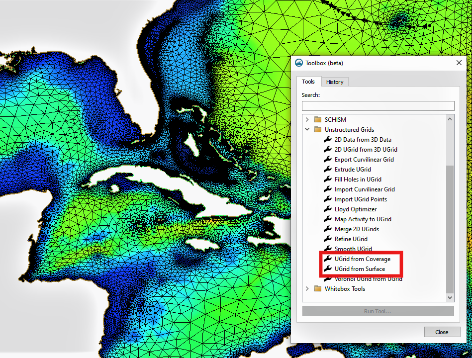
UGrid creation tools in SMS 13.3

The first UGrid creation tool we will explore in this blog post is the UGrid from Coverage tool. The UGrid from Coverage tool takes the feature objects on a selected coverage and generates a UGrid from the properties of those feature objects. The tool can work with multiple coverage types. Like using the mesh generator coverage to create 2D meshes, the spacing of vertices on the arcs will determine the refinement of the generated UGrid. To generate a UGrid, the coverage must have at least one polygon in it. The parameters required when executing the tool are a coverage, and a name for the new UGrid. We recommend choosing a name that is short, but references the input data for easy reference.

The second UGrid tool we will explore is the UGrid from Surface tool. The UGrid from Surface tool takes an existing mesh, scatter set, or Cartesian grid and creates a new UGrid with copies of all of the datasets. This can be useful because it changes the data into a form that can be modified and manipulated while still preserving the original data. The input parameters include an input mesh, scatter set, or Cartesian grid, and an output grid name. Again, we recommend choosing a name that is short and references the input data.

All of the UGrid tools are accessible by clicking on the toolbox macro at the top of the window, then expanding the Unstructured Grids folder.

Download the SMS 13.3 beta and explore how the UGrid from Coverage and UGrid from surface tools, as well as the numerous other UGrid tools, can help your project today!

Blog tags: 

Announcing SMS 13.3 Beta

Our developers have been hard at work making improvements and expanding the functionality of SMS. Aquaveo is happy to announce the release of the beta version of SMS 13.3!

To show you some of the things you'll see in this version of SMS, we've compiled a short list of some of the new features included in this release.

Improvements to SRH-2D

In SMS 13.3 beta, we have added support for the use of unstructured grids (UGrids) in SRH-2D modeling and simulations in addition to meshes. SRH-2D also now supports the use of DIP files in its modeling, and we updated the scour calculator. We also updated the model execution to eliminate false positives and SRH-2D will only call HY-8 one time when running multiple simulations which removes the possibility of collisions.

Changes in the Toolbox

If you visit the Toolbox in SMS 13.3 beta, you'll find that it has been reorganized and some of the naming conventions have been changed, as well as an added folder for 2D Mesh tools. If you can't find a tool that you've used in previous versions, don't worry. All the same tools are available to you, it may just be under a slightly different name or in a different folder.

New Tools

There are also several new tool options in the Toolbox. This includes, but is not limited to:

  • Polygons from UGrid Boundary: converts the outer boundary of a UGrid to polygons in a new coverage. This tool only functions on UGrids with 2D Cells.
  • Fill Holes in UGrid: fills all voids in a given mesh with new mesh elements. The output is a mesh that can be converted back into a UGrid if needed. This tool also works on meshes.
  • Refine UGrid: create a 2D UGrid that has been refined based on an existing 2D UGrid and one or more elevation rasters.
  • Curvilinear Grid tools: import and export a curvilinear grid in the form of a CH3D or EFDC file.
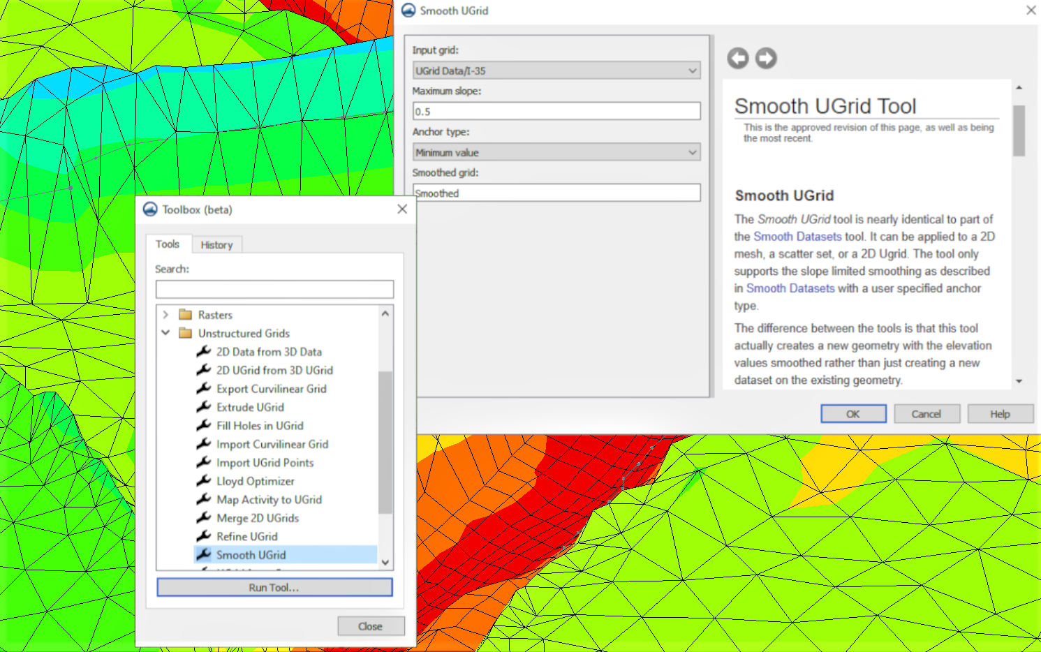
Example of the Smooth UGrid Tool in SMS

As always, the help button in the tool dialog will direct you to a page on our wiki that will give you a more thorough description of the tool and its function.

The Community Edition of SMS 13.3

One of the major changes in SMS 13.3 beta is that we have made four models available in the free community edition of SMS. New models that are now included in the community editions are:

  • ADCIRC (ADvanced CIRCulation): a hydrodynamic model used for modeling oceans, inlets, rivers, and floodplains.
  • AdH (Adaptive Hydraulics): a model used for groundwater and overland flow.
  • CMS-Flow: used for more local modeling, mainly for inlets, the nearshore, and bays.
  • STWAVE (STeady State Spectral WAVE): models wave refraction, shoaling, breaking, diffraction, wind-driven wave growth, and wave-wave interaction with energy redistribution and dissipation.

These are only a few of the new features offered in SMS 13.3 beta. You can find the list of all new features on this page of our wiki. Try out SMS 13.3 by downloading it today!

Blog tags: 

Pages