SMS

Associating HY-8 Files with SMS

Have you wondered about how HY-8 interacts with SRH-2D in SMS? This post will review what HY-8 and SRH-2D are doing as they interact with each other.

SRH-2D has an option to use the HY-8 software to define culverts. Using the HY-8 software allows for greater definition for the culvert as opposed to defining the culvert directly in SMS. The Launch HY-8 button in the SRH-2D Assign BC dialog creates the HY-8 file and associates the file with the culvert arcs and SMS project. It is important to keep this file with the SMS project, otherwise the HY-8 file may become unassociated with the culvert.

Multiple culverts can be in the same HY-8 file, so be certain the correct culvert has been associated to the culvert arcs in SMS.
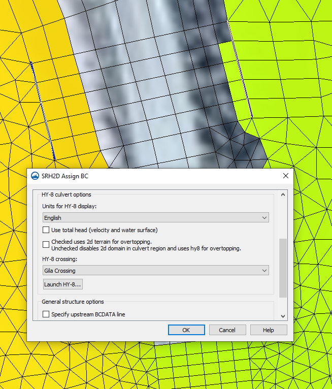
SRH-2D culvert using HY-8

When assigning properties to arcs that have been set to a BC Type of Culvert HY-8, there is a checkbox option to turn on 2D terrain for overtopping. When this is unchecked, SRH-2D will create a *_HYn.dat for the crossing. When this is checked, SRH-2D will instead create an *_INTERNALn.dat file for the crossing. In this case, SRH-2D will use the HY-8 table, but won’t see the structure as a HY-8 culvert, but as essentially a link structure.

Typically, the overtopping option is used when overtopping flow is expected to travel in a different direction from the rest of the flow. If the flow over the culvert and the flow in the culvert are both flowing in the same direction, it is not recommended to use 2D Overtopping. This is because the link structure in SRH-2D can get flow from both upstream and downstream of the boundary arc and the flow coming out of the downstream arc can go in any direction.

When SRH-2D runs, it will generate output files that are sent to an Output_MISC folder in the file directory of your current SMS project. Here, HY-8 culvert report files and/or pressure flow overtopping report files should be found, following the respective naming schemes of “*_HYn.dat” and “*_INTERNALn.dat”. The “*” is a placeholder for the specific case name specified in the model control, and the “n” will be replaced with a number in a series, for as many relevant zones or arc pairs exist in the series. We unfortunately don’t have any control over the naming convention SRH-2D uses.

More information about the different types of SRH-2D output files that may be put out after an SRH-2D run can be found here at the Aquaveo XMS Wiki.

Try out using HY-8 with SRH-2D in SMS 13.1 today!
Blog tags: 

Understanding SRH-2D Post-Processing

Do you want to know more about what happens when SMS completes post-processing for SRH-2D? When running SRH-2D, it helps to understand what exactly is happening during the post-processing phase of the SMS model run. This post will review how post-processing uses interpolation as it goes through SRH-2D.

To understand how post-processing fits into the SRH-2D process, first we need to look at what comes before it. When creating an SRH-2D model in SMS, the data is assigned as nodal data. This means that the boundary conditions, materials and other data is assigned to the nodes of the mesh. SRH-2D requires that the data be assigned to the center of the mesh elements (the centroid).

To allow the nodal data to be used by SRH-2D, SMS uses a pre-processing step that utilizes linear interpolation to interpolate the data that has been modelled in SMS into centroidal data for SRH-2D to use. After SHR-2D has finished processing the data, it creates results that use centroidal data. This is where the post-processor comes in.

The post-processor for SRH-2D takes the SRH-2D results and interpolates the data from centroidal data and converts it into nodal data. This allows SMS to import and display the solution data.

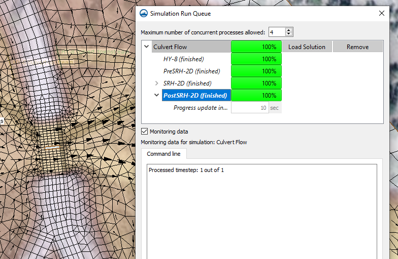
Post-processing for SRH-2D

If the post-processor fails in its attempt, this usually means the centroidal data generated from SRH-2D is not valid. In this case, it could be possible that the model failed to converge even if SRH-2D managed to completely finish its model run. It could also be possible that SRH-2D was made to run an invalid model that resulted in empty solution sets.

For more information on how to use SRH-2D with SMS, see the XMS Wiki article on SRH-2D in SMS. Future versions of SMS may make use of centroidal data without the need to interpolate data.

Now that you understand a little more about how SMS handles post-processing, try out SRH-2D in SMS 13.1 today!

Blog tags: 

Understanding SRH-2D No Flow Boundaries

Do you want to understand more about how SRH-2D uses no flow boundaries? Occasionally, you can encounter various challenges regarding no flow boundaries. This post will review how no flow boundaries interact with SRH-2D in order to avoid potential issues with your SRH-2D model.

Examples of no flow boundaries in SRH-2D

SRH-2D includes different types of no flow boundaries such as:

  • Boundary condition arcs assigned to be a "wall".
  • The elements touching a void in a mesh.
  • The boundaries of a mesh that are not assigned to be inflow, outflow, etc.

Make certain to review all of your no flow boundaries. In particular, if you used a shapefile or another coverage to create your boundary condition coverage review all of the arcs on the coverage. In SMS, the default SRH-2D boundary condition is a "wall", so any arcs on the boundary condition coverage that are not meant to be no flow arcs should be changed or removed. A wall arc will snap to the nearest mesh boundary or void boundary. A wall arc should not be used to define an internal no flow area.

An important aspect to understand for no flow boundaries is that for every element they touch, SRH-2D is essentially being told that water can't flow past the boundary. This changes how SRH-2D computes the flow of water through the model. Large elements that are part of no flow boundaries can impact the model flow more than desired, because the smallest unit SRH-2D can process is a single element. SRH-2D is not designed to assign multiple flow values to a single element.

With this restriction on flow for single elements in mind, large elements can have a disproportionate effect on the model if left in key areas. Therefore, in most cases it is important to make sure that elements around key areas of the model should be more refined. Larger elements should be left in less important areas where they will have less impact.

Now that you understand a little more about no flow boundaries, try out SRH-2D in SMS 13.1 today!

Blog tags: 

Using BCDATA Lines with SRH-2D

Have you needed to modify how SRH-2D calculates flow around a structure? Using BCDATA lines in SMS may be able to help. New to SMS 13.1, the BCDATA line feature lets you specify a location where a water level or flow rate is extracted for a variable boundary condition.

The BCDATA line is primarily used to adjust how flow is calculated going into or leaving a structure. If there is high skew or rapid drawdown at the entry or exit of the structure then you should consider using a BC Data line. It indicates that rather than performing flow computations directly at the site of the structure, they should be performed at the location of the BCDATA line.

There are a few applications for a BCDATA line. For instance, it can be used on a structure such as a weir or culvert. When SRH-2D computes flow through or over a structure, it uses an average water surface elevation. When no BCDATA line is present, SRH-2D computes right along the nodes where the upstream boundary condition arc has been mapped. If an upstream or downstream BCDATA line exists, the water level can be computed there rather than at the actual edges of the structure. The BCDATA line should typically be located one or two cells upstream or downstream from the structure to get out of the zone of influence of the structure itself. This avoids drawdown caused by the flow going through or over the structure.

To create a BCDATA line and assign it to a structure, use the following workflow:

  1. Use the Create Feature Arc tool to create a line a few elements long, ideally about 1 to 2 elements away from the upstream or downstream arc. Create it perpendicular to the arc and along the centerline.
  2. Using the Select Feature Arc tool, select the line you have just created, right-click it, and select Assign BC… to bring up the SRH2D Assign BC dialog.
  3. Set the BC Type to Bc Data. Make sure to provide a label name that is unique in the coverage. Then click OK to close the dialog.
  4. Now select the upstream or downstream arc that is meant to be associated with the BCDATA line, right-click it, and select Assign BC… to bring up the SRH2D Assign BC dialog.
  5. Scroll down to the General structure options section at the bottom. Depending on whether the arc selected is upstream or downstream, check the box by the appropriate BCDATA line option.
  6. Use the drop-down that populates to select the label you previously specified for the BCDATA line. Then click OK to close the dialog.

The BCDATA line will now be assigned to the structure.

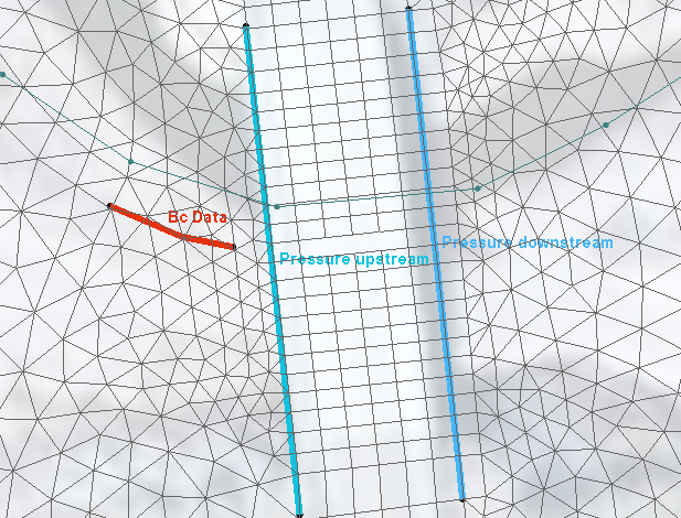
Example of a BCDATA Line

It can also be used on a Link or an EXIT-H boundary condition that you have specified using a rating curve. Normally, without a BCDATA line, SRH-2D computes the average flow directly at the line and then extracts the water level from the curve. When a BCDATA line does exist, the flow rate (Q) is computed across the BCDATA line, like a monitor line, rather than exactly at the boundaries.

Try using BCDATA lines with SRH-2D in SMS 13.1 today!

Blog tags: 

Pages