SMS

Converting Soil Data to an Index Map

Do you need to add soil data to your GSSHA model in WMS? Soil data is often needed in a rainfall/runoff GSSHA model so that infiltration can be considered in the model. WMS makes this easy by allowing soil data to be converted to an index map.

In order to include soil data in your GSSHA model, there are few steps to follow.

First, you will need a soil data map coverage. Once this coverage has been created you can add soil data directly to the map coverage. Often, you may have soil data located on a shapefile or other source. The soil data on the shapefile needs to be mapped over to the soil data coverage before creating the index map.

Second, the index map will be included with a 2D grid for the GSSHA model in WMS. Make certain you have created your 2D grid and initiated your GSSHA model.

Finally, convert the soil data coverage to be an index map in your GSSHA project. This is done by doing the following:

  1. Use the GSSHA | Maps command.
  2. In the GSSHA Maps dialog, set the soil data coverage to be used.
  3. Click the Coverages to Index Map button.
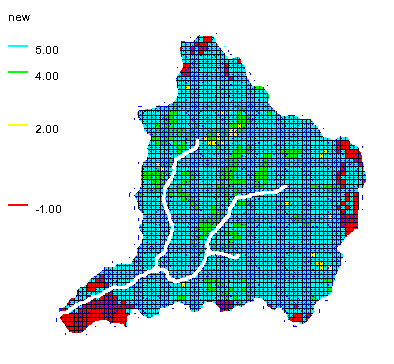
Soil data converted to an index map

Once you have converted your soil data to an index map, you can use it in your GSSHA model.

When converting soil data to an index map, we do have some tips to make it go smoother.

  • When converting a shapefile to a soil data coverage, make certain that the soil data with the shapefile has been joined to the shapefile.
  • After mapping a shapefile to a soil data coverage, make certain that the soil data mapped over.
  • Check to see if soil covers the entire area of the 2D grid. A warning may appear if the soil data does not cover the area of the 2D grid.

Once your soil data have been successfully converted to an index map, it is ready to be used in your GSSHA model.

Try out using soil data with GSSHA in WMS today!
Blog tags: 

New Map Annotation Tools in SMS 13.1

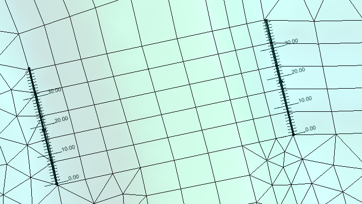
With the release of SMS 13.1 beta, a new tool has been added to allow you to have additional annotations on feature objects. SMS already provides several options for adjusting how feature objects are displayed, but now more options exist specifically for feature arcs to help make working with feature arcs easier.

Currently in recent versions of SMS, annotations can be added to label arcs. This would let you see the name of specific arcs. The color and thickness of feature arcs can also be changed. Also, specific annotation options exist for specific model coverages, such as the SRH-2D boundary conditions map coverage.

The new map annotations can add a number of new annotations to your feature arcs.With the new annotation tools, the following can also be displayed:

  • An arrow indicating the the direction of the feature arc
  • Tick marks to indicate the distances along the arc
  • The length and number of tick marks can be adjusted along the arc
  • Tick mark labels can be added
  • The font and color of tick mark labels can be changed
Map module annotations in SMS 13.1

These options allow you to quickly see if an arc has been placed in the wrong direction or to check the measurement of an arc. Note that tick marks will use the units set in the project's projection.

To activate the map annotations, do the following:

  1. Open the Map Display Options
  2. Turn on the Annotations option under the Arcs section
  3. Click the Options button next to the Annotations option
  4. Turn on the different the map annotations options in the Arc Annotations Options dialog

Note, with the exception of the tick mark color, that the line width and color are still determined by the other arc display options. The display of the arcs can be adjusted before or after setting the arc annotation options.

Try out the different map annotation options in the SMS 13.1 beta today!

Blog tags: 

Using the Temporal Tools in the Dataset Toolbox

SMS contains several ways to work with datasets. Perhaps the most useful of these is the Dataset Toolbox. The Dataset Toolbox has several tools for generating new datasets. Among these are the temporal tools which allow adjusting the time steps for a transient dataset. The temporal tools include two options: Sample Time Steps and Merge Dataset.

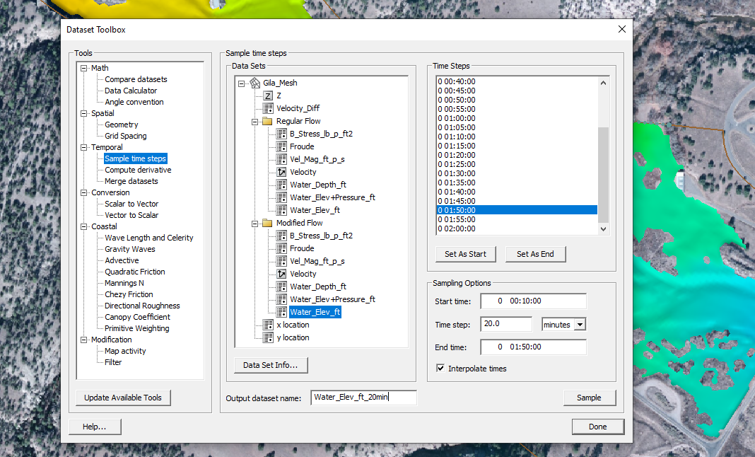
The Sample Time Steps tool allows the creation of a dataset with a different number of time steps. The time steps can either be increased or decreased. To use the Sample Time Steps tool:

  1. Open the Dataset Toolbox and select the Sample Time Steps tool.
  2. Select the transient dataset you want to use.
  3. Select the starting and end times.
  4. Enter the time step frequency and units.
  5. Give the new dataset a name and click Sample.
Dataset Toolbox showing the Sample Time Steps tool

The other temporal tool is the Merge Dataset tool. This allows us to combine two transient datasets. To use this tool, the transient datasets being combined cannot have overlapping time steps. Most often, this tool is used to append multiple simulation runs together.

For example, if you completed an SRH-2D model run for one day, then created a new simulation for a second day (using a hot start file from the end of the first day simulation run), you could combine the results of the two simulation runs using the Merge Dataset tool.

To use the Merge Dataset tool:

  1. Open the Dataset Toolbox and select the Merge Datasets tool.
  2. Select the first dataset to use, then select the second dataset.
  3. Enter a name for the combined dataset and click Compute.

When using the Merge Dataset tool, make certain that the first dataset selected has time steps that are earlier than the second dataset selected.

The temporal tools in the Dataset Toolbox provide a simple way to adjust transient datasets in your project. Try using these tools in SMS today!

Blog tags: 

Viewing Vectors on the Watersurface

With the release of SMS 13.1 beta, a new option has been added to the Vector tab. The existing Vector tab in the Display Options dialog allows viewing vector data as arrows as data points in your project. SMS can change the density of how the vector arrows are displayed and to display the vector arrows along a constant elevation. This new option allows you to display the model vectors relative to a selected dataset.

To use this option:

  1. Open the Display Options, turn on vectors, and go to the Vector tab.
  2. On the Vector tab and change the Origin to be "Relative to dataset".
  3. Select the Dataset button under the Origin to bring a tree item selector dialog.
  4. Select the Dataset you want to use.

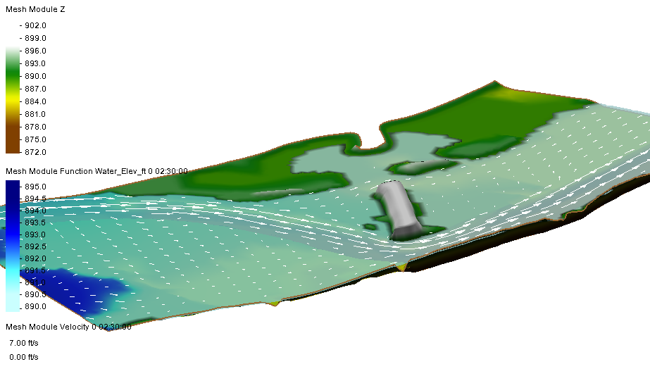
After closing out the Display Options dialog, you will be able to see the vectors relative to the selected dataset. For example, if you use a water surface elevation dataset, you would be able to see the vectors relative to the water surface elevation.

Vectors relative to the water surface elevation

This option is available for all modules that allow displaying vectors. This includes the 2D mesh module, Cartesian grid module, quadtree module, and scatter set module.

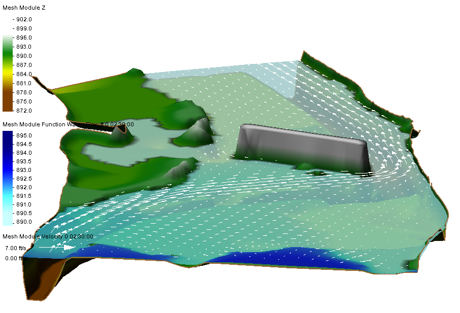
There is also an option to specify an offset for the selected dataset. For example, you could set the offset to 1 or 2 to get the vectors slightly above the surface. The result would show the vectors mapped 1 or 2 feet above the ground elevation.

Vectors offset from ground elevation

This addition to the vector display option can be used with any dataset in the same module. Therefore, any dataset in the mesh module can be used with a mesh, any dataset in the scatter module can be used with a scatter set, etc.

Try out using the new "Relative to dataset" vector display option in the SMS 13.1 beta today!

Blog tags: 

Pages