SMS

How to Relax or Refine a Mesh in SMS

Are you ever tempted to refine your mesh after creation using the mesh editing tools? Manually changing hundreds or thousands of mesh elements using the mesh tools can be very time consuming.

Although possible to use the mesh tools, it is better to recreate a new mesh when wanting to refine or relax the elements. This will maintain the accuracy of your mesh, and reduces possible issues that may arise later on in the project due to inconsistencies that editing manually creates.

To recreate a refined or relaxed mesh:

  1. Create a mesh generator coverage.
    1. If the existing mesh was created from a mesh generator coverage, you can use that coverage or a duplicate of that coverage.
    2. If a mesh generator coverage does not exist, you can create a mesh generator coverage by converting the mesh boundary or nodestrings to a new mesh generator coverage.
  2. Go to your mesh generator coverage and redistribute the vertices so that there are either more or less arc segments depending on what you are trying to accomplish with your model. To relax the mesh, fewer arc segments are desired, and to refine the mesh more arc segments are desired.
  3. Assign the desired meshing type (paving, patch, etc.) to the polygons in the mesh generator coverage and set the bathymetry source to use. Be certain to preview how the mesh will generate with the new spacing for each polygon.
  4. Now generate a new 2D mesh using the edited mesh generator coverage.
  5. Add the new mesh to your model simulation and run the model using the relaxed or refined mesh.
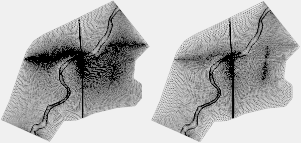
Sometimes you might not want to relax ro refine the entire mesh. To only relax ro refine part of the mesh do the following.

  1. Create a new mesh generator coverage.
  2. Create a polygon in the area of the mesh you wish to relax or refine.
  3. Redistribute the vertices along the arcs in the polygon to so there is a great or fewer number of segments along each arc.
  4. Set the meshing type for the polygon and assign it a bathymetry source. Be certain to preview the mesh for the polygon to be certain you are getting the mesh you want.
  5. Generate a new 2D mesh for the area being refined or relaxed.
  6. Select both 2D meshes and merge them together.
  7. Add the new merged mesh to your model simulation and run the model.

Using these steps when editing a mesh can make a huge difference in your model and save you time. Try out relaxing and refining meshes in SMS today!
Blog tags: 

Moving SRH-2D Material Attributes to Another Project

After setting your SRH-2D material attributes in one SMS project, have you ever wanted to transfer those attributes to another SMS project? Doing this can save you from having to reenter the same material attributes into a separate project. You can even transfer multiple material coverages at once.

There are three project files referred to here: the original project, the project with the saved material coverage attributes, and the third project to which you want to add the saved material attributes. To make sure these instructions are clear, we'll call them Project A, Project B, and Project C, respectively.

To save time on other projects that use the same material attributes, you can use the following steps to export them for later use:

  1. Outside SMS, create a copy (Project B) of your project directory. This prevents you from accidentally damaging the original project (Project A) during the process.
  2. In Project B (the copy), delete any geometric data that isn’t going to be transferred, such as meshes, grids, GIS data, and scatter sets.
  3. Also remove any coverages and material data you do not want transferred.
  4. On the SRH-2D material coverages, remove any polygons and feature objects that you do not want transferred. This is assuming that the project receiving the new material parameters will be assigning the material properties to different polygons.
  5. This is the tricky part. You have to have at least one Map object for a map file to be saved in SMS. Therefore, create a new coverage of any type as a placeholder. Create a single feature point in this placeholder coverage.
  6. Use the Save command to save Project B that only contains the SRH-2D material coverages with your material properties, and one one other coverage with a single feature object.
  7. In another instance of SMS, open Project C.
  8. Use the Open command to open Project B.
  9. SMS should ask if you want to delete this data. If this happens, respond "No". The coverages from Project B (and its material lists and attributes) will be loaded into Project C.
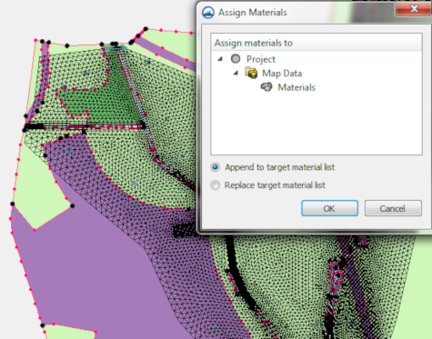
  10. Now to add the material lists from the Project B into the material lists in Project C by right-clicking on the transferred coverage and selecting the Assign Materials to menu command. SMS will bring up the Assign Materials dialog where you can add materials from one coverage to another. You can either add the materials to the list of this coverage or replace the materials list in this coverage.

Now that you know how to transfer material parameters from one project to another, try it out in the SMS today!

Blog tags: 

New Bridge Scour Tool in SMS 13.0

You are probably aware of the potential destruction caused by bridge scour. Up to 60 percent of bridge failures in the United States from 1950 to 1989 were caused by scour. Bridge scour occurs when the stream bed material around bridge piers is eroded. This can leave the pier unsupported by the stream bed, causing it to collapse.

Recent news has shown bridges of all sizes all around the world collapsing or in danger of collapsing due to scour. Such failures can have a huge negative impact on the economy and also pose a danger to the lives of those who use the bridge regularly. The Federal Highway Administration (FWHA) advised that it is far less expensive to take measures to prevent scour than to replace a bridge that fails due to scour.

Part of the scour mitigation process is evaluating countermeasures that can be taken to prevent such failures. These include onsite surveys and inspections, physical modeling such as that done at the FWHA Hydraulics Laboratory at the Turner-Fairbank Highway Research Center in McLean, Virginia, and computer modeling using tools such as the Surface-water Modeling System (SMS) from Aquaveo.

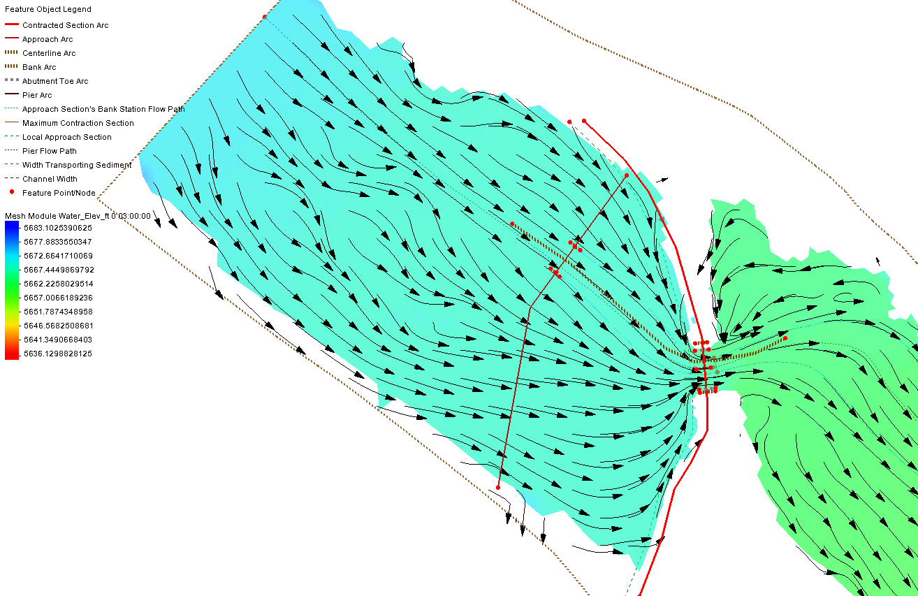
SMS 13.0 adds powerful new post-processing Bridge Scour tools that can be used to quickly test the scour effect of different pier arrangements, pile sizes and shapes, and vessel impact protection structures such as dolphins and fender rings. The Bridge Scour feature in SMS 13.0 can be used with the FWHA Hydraulic Toolbox to take advantage of its various bridge scour calculators and mapping tools.

One of the most exciting features of Bridge Scour is how it saves time. When creating the contracted section, approach, centerline, bank, abutment toe, and pier arcs, SMS 13.0 automatically assigns the arc type if they are created in order. This translates into saved time and cost, allowing you to be more productive.

Check out the Bridge Scour tool in the SMS 13.0 beta.

Blog tags: 

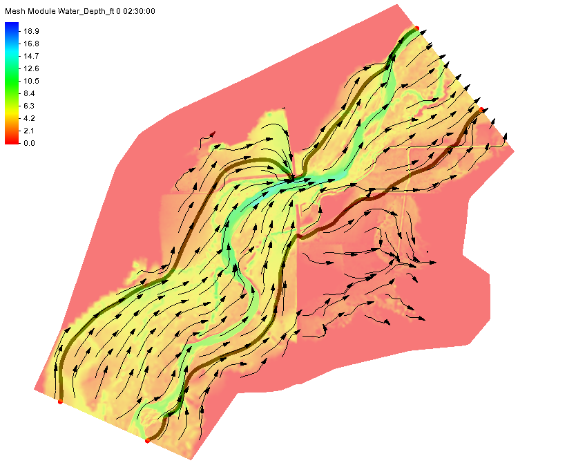
New Floodway Delineation Tool in SMS 13.0

City planners, developers, and others have a great interest in using available land. Sometimes that land is close to areas that flood, so precautions need to be taken so the build site is not too close to (or directly in) the potential flood area. Failure to properly plan and delineate a floodway can potentially cause millions of dollars in flood damage as well as potential losses in property values. Hurricanes Harvey and Florence, with their extreme rainfall amounts, are prime example of why floodway delineation is so important.

In addition to the guidance provided by the Federal Emergency Management Agency (FEMA), the new Floodway tool in SMS allows the extents of a floodway area to be more clearly defined. This tool allows planners, developers, and others to run multiple simulations to determine the safest places to build as well as the places which may be most impacted during a significant flooding incident.

To use the Floodway tool in SMS, a project must have a either a Cartesian grid, a 2D mesh, or a 2D scatter set that has simulation result datasets for at least water depth and velocity. Two coverages are also required: a 1D hydraulic centerline coverage and a 1D hydraulic cross section coverage.

The way the Floodway tool works is by calculating how far in from both sides of a river or stream that vertical walls can be placed and raise the center of flow by the targeted maximum rise. FEMA suggests this rise should be no more than 1 foot. These calculations use the input provided by the water depth dataset, the velocity dataset, and the two hydraulic coverages to define the floodway extents along the entire length of the study area.

Once these extents are known, the data can be used when making area planning and development decisions at all levels of government and businesses. You can try out this feature in SMS 13.0 beta today.

Blog tags: 

Pages